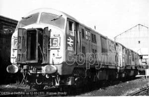
Profile of a Class 22 diesel
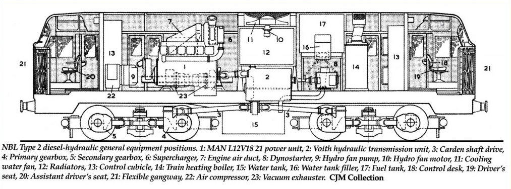
You’ve seen the pictures, but what’s “under the hood” of a Class 22 locomotive? On the cut-away drawing immediately below, use your mouse to select a part number in order to go directly to its description, or simply scroll down the page.
No.1
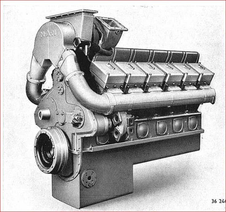
Item Description : Engine, NBL/MAN L12V 18/21BS
Operation: The power unit is 12 cylinder, V form with 6 cylinders per bank and operates on the 4 stroke cycle. Exhaust turbo charged using the pre-combustion chamber principle
Note: We own engine 220
No. 2
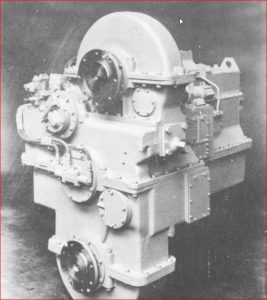
Item Description : Voith-N.B.L. LT 306r hydraulic Transmission
Operation:
Note: A Voith LT306 presently still eludes us. We are on the hunt for this transmission; presently looking towards Italy and Germany as there are still a number of DB 200 diesel hydraulic locos with this transmission there.
No. 3
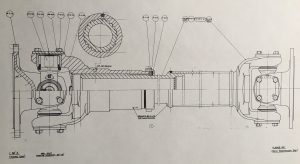
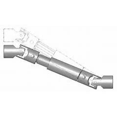
Item Description: Cardan Shafts (6, Hardy-Spicer)
Operation: A cardan shaft is a mechanical component for transmitting torque and rotation, used to connect the transmission to the gearboxes and the engine to the transmission. This is employed when other components of a drive train cannot be connected directly because of distance or the need to allow for relative movement between them.
Note: Hardy-Spicer, the original producer of the Class 22 shafts, are still in business. We will have all our shafts built from new specifications to fit our locomotive.
No. 4
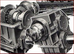
Item Description: Primary Gearbox, David Brown double reduction final drive
Operation: The primary gear box is connected to the transmission via a cardan shaft. It is bogie mounted. The final drive is that part of a power transmission system having the function to change the direction of the power transmitted by the drive shaft through 90 degrees to the driving axles. At the same time it provides a fixed reduction between the speed of the drive shaft and the axle driving the wheels
No. 5
Item Description : Secondary Gearbox, single reduction final drive
Operation: David Brown primary gearboxes, single reduction final drive. The secondary gear box is connected to the primary gearbox through cardan shafts. It is also a part of the bogie and connected to the leading wheel set
No. 6
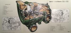
Item Description: Supercharger. Napier Turbocharger MS200
Operation: A compressor driven by the exhaust gasses used that optimises the pressure and mass of the inlet air in the fuel air mixture to increase engine power
Note: We have one attached to our engine, that will probably need an overhaul
No. 7
Item Description: Engine air duct. Air inlet duct from body side filters to turbocharger
Operation: Ducts clean air via the filter system to the turbocharger inlet ducts.
Note: This will need to be fabricated specially
No. 8
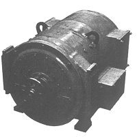
Item Description: Dyno-starter. Generator/Starter
Operation: A dual-purpose electrical machine used to crank the engine during the start-up process, then switched by the control gear to act as a dynamo to charge the batteries and run electrical systems when driven by the engine.
Note: This is no longer manufactured, so an alternative will need to be sourced.
No. 9
Item Description: Hydro Fan Pump. Pump for Hydro-static fan drive
Operation: Provides a high-pressure oil supply to drive the cooling fan motor. In the Class 22’s this was a constant source of problems.
Note: This is a part of the cooling system.
No. 10
Item Description: Hydro Fan Motor. Motor for Hydro-static fan drive
Operation: Uses high-pressure oil from the pump to drive the engine room cooling fan, depending on the load.
Note: This is a part of the Cooler Group.
No. 11
Item Description: Cooling Water Fan. Fan for the Cooler Group
Operation: Large diameter fan driven by the hydro-static pump to force cooling air through the radiators.
Note: This is a part of the Cooler Group.
No. 12
Item Description: Cooler Group.
Operation: Radiators and associated equipment for keeping the engine cool.
Note: Compatible modern components are available.
No. 13
Item Description: Control Cubicle. Fabricated part – contains BBC control gear
Operation: Contains all control systems for the operation of the locomotive.
Note: To be manufactured afresh using compatible modern components.
No. 14
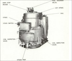
Item Description: Train Heating Boiler. Stone Vapor OK4610 or Clayton AO 1000
Operation: Burns fuel oil to provide steam at high pressure. Used to heat coaching stock.
Note: There are no present plans to include one, as it will depend on availability of a secondhand item.
No. 15
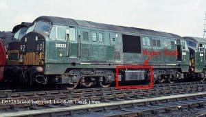
Item Description: Water tank.
Operation: Provides boiler water for the steam heating boiler
Note: One will be required for appearances’ sake, whether operational or just dormant
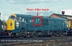
No. 16
Item Description: Water Tank Filler. A filler assembly for the steam heat boiler water tanks
Operation: Provided to replenish the water used for steam heating of the stock, often via locomotive water columns.
No. 17
Item Description: Fuel Tank. The main fuel tank for the engine and steam heat boiler
Operation: Storage for diesel fuel, 450 gallons.
Note: Fabricated item.
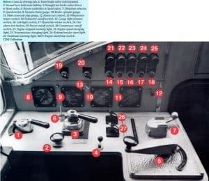
No. 18
Item Description: Drivers Control Desks
Operation: Contains all switches, warning lights, gauges and controls for the operation of the locomotive.
Note: These will be freshly fabricated items.
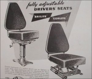
No. 19
Item Description : Driver’s Seats. Widney seats – several different types were used
Note: Used on other locomotive types and should be available.
No. 20
Item Description : Second Man’s Seats. Widney seats – several different types were used
Note: Used on other locomotive types and should be available.
No. 22
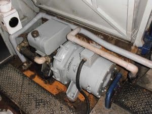
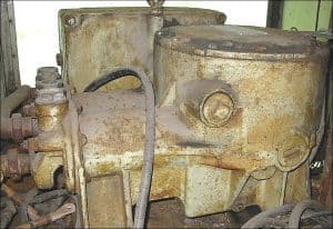
Item Description: Air Compressor. Westinghouse CM38
Operation: This provides compressed air for use in control and locomotive braking systems.
New: Alternatives can be found. (The picture shown is a Westinghouse CM38)
No. 23
Item Description: Vacuum Exhauster. Reavell FRU 5 1/4 x 10
Operation: Used to create vacuum for the train braking system
Note: These were used in various locomotive types, so alternatives can be used
